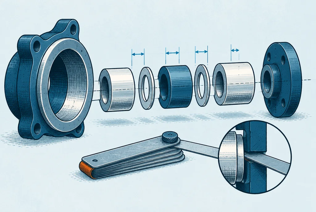
Draw the functional gap first
A tolerance stack is easiest to understand when tied to a physical question: will the slider enter, will the lid close, or will the fastener have enough engagement? Sketch the assembly in the relevant direction and mark the gap or overlap that determines success. Avoid collecting unrelated dimensions simply because they appear on a drawing.
Identify the surfaces that actually locate the parts. If a component seats on a shoulder, dimensions should be related to that shoulder rather than an arbitrary outer edge. A chain measured from cosmetic surfaces can obscure the functional relationship. Autodesk's tolerancing guidance provides the broader context for communicating allowable geometry; the calculation below is a deliberately simple linear example.
Use minimum and maximum values in the same units. A nominal dimension alone is not a tolerance. Supplier defaults may apply differently to machined, printed, and molded parts, so obtain the applicable capability and acceptance agreement before treating a default as guaranteed.
Work through a hypothetical sliding fit
Suppose a channel width is 20.40 ±0.15 millimeters and a slider width is 20.00 ±0.10 millimeters. The smallest channel is 20.25 millimeters and the largest slider is 20.10 millimeters. Minimum clearance is therefore 20.25 minus 20.10, or 0.15 millimeters. Maximum clearance is 20.55 minus 19.90, or 0.65 millimeters.
The nominal clearance is 0.40 millimeters, but that single number conceals the range. If the intended function needs at least 0.25 millimeters, the specified dimensions do not meet that requirement in the worst case. If excessive looseness becomes objectionable above 0.55 millimeters, the other end also needs attention. These limits are invented for the example, not recommended sliding-fit values.
Now add a hypothetical coating that reduces the opening by a total of 0.04 millimeters across its two faces and increases the slider width by 0.02 millimeters. Minimum clearance falls to 0.09 millimeters. The coating must be included with its own variation if it matters. Do not subtract a per-face thickness once when the geometry contains two affected faces.
The calculation still omits straightness, angular misalignment, local defects, thermal change, and surface texture. A positive linear clearance is necessary for some fits but is not sufficient proof that a real assembly will slide smoothly.
Fix the dominant contributor rather than every dimension
Compare the contribution of each dimension to the range. If one dimension dominates, ask whether its function justifies a tighter process or whether the design can accommodate variation. A small geometric change, a compliant feature, or a different locating arrangement may be less expensive than imposing tight tolerances on every surface.
Avoid a universal tight tolerance in the title block. It can increase cost on features that do not affect function while failing to control an important geometric relationship. Specify critical features deliberately and discuss their inspection method with the supplier. A tolerance that cannot be economically measured may create disputes without improving the product.
Revisit the interface architecture. Two parts can sometimes share a common datum, use one locating feature instead of several competing ones, or gain an adjustment feature. These approaches change the stack itself. They require engineering review but may remove sensitivity more effectively than demanding exceptional manufacturing accuracy.
Know when statistical stack-ups are inappropriate
Root-sum-square calculations are often presented as a convenient way to obtain a smaller range. They are not a license to ignore worst-case combinations. Their usefulness depends on assumptions about distributions, independence, centering, and the acceptable probability of failure. Small prototype samples rarely establish those assumptions well.
If parts come from one biased setup or mating dimensions are correlated, a simplistic statistical model can mislead. For an early invention, calculate the transparent worst-case result first. Use statistical analysis only with the relevant process evidence and a person who understands the consequences of the chosen model.
For safety-sensitive interfaces, rotating assemblies, press fits, seals, or geometrically complex parts, a one-dimensional spreadsheet may be inadequate. Define the analysis boundary and obtain appropriate engineering support rather than extending a beginner calculation beyond its scope.
The fit worksheet to keep with your CAD
Record the functional requirement, sketch, dimension sources, nominal values, limits, sign convention, finish effects, and calculated gap range. Add a row for excluded effects and the planned physical check. Version the worksheet with the design so a later geometry change does not leave the calculation stale.
Measure prototype parts individually before trying to assemble them. If a fit fails, those measurements help distinguish a design issue from a part outside its agreed limits. Preserve combinations that work and fail; selective pairing can hide a stack problem that will return in production.
The deliverable is a traceable explanation of why the chosen dimensions should fit, plus a test of the actual interface. Neither the nominal CAD assembly nor one fortunate pair of parts provides the same evidence.