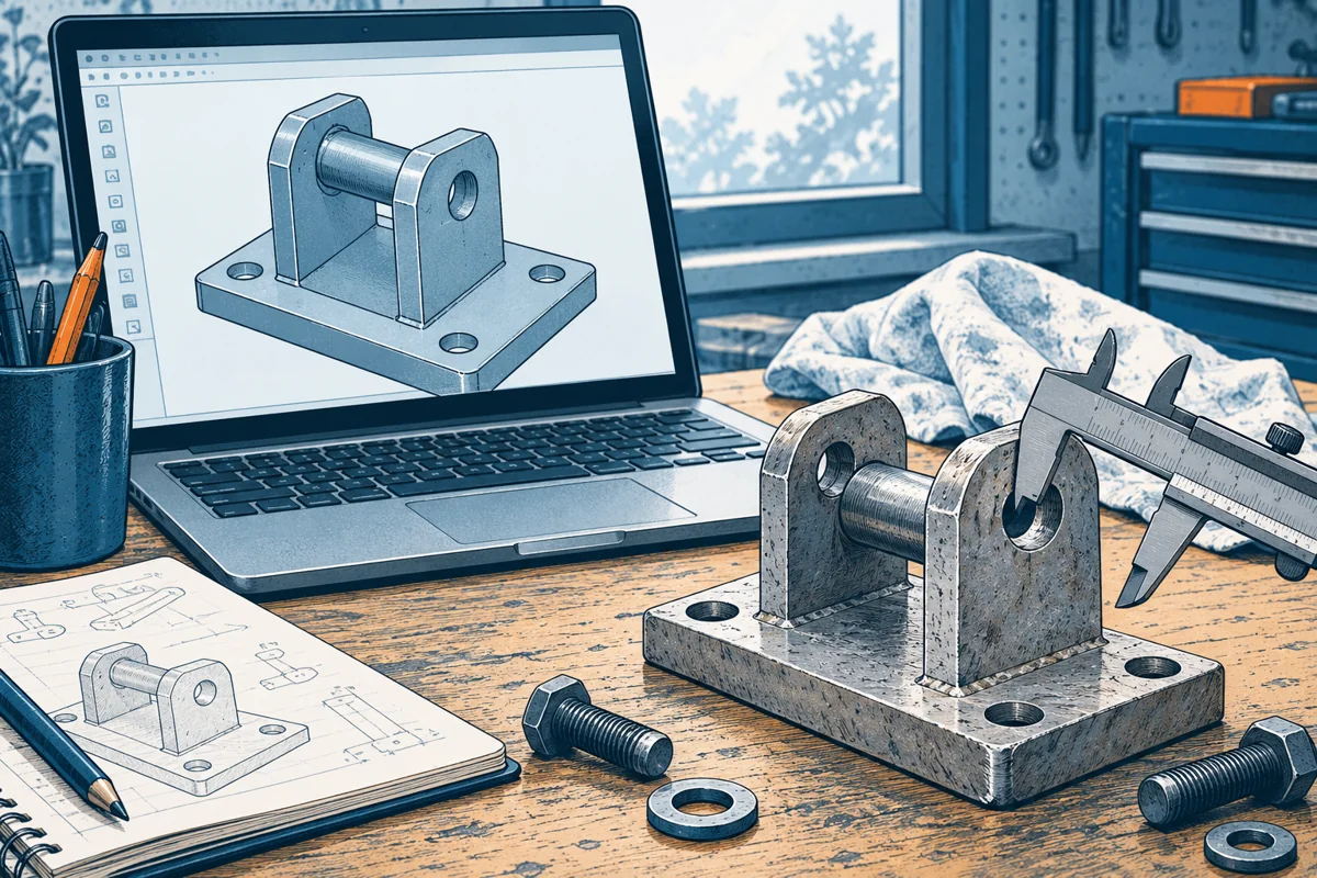
Preserve the failure before repairing it
When two new parts refuse to mate, the temptation is to file, drill, or force them together. That may produce a demonstration unit while destroying the evidence needed to correct the design. Photograph the interference, label the parts, and record the exact combination and orientation before making modifications.
Confirm that both parts match the same released assembly revision. An older lid and newer base can fail even when each was manufactured correctly. Check file units and overall scale. Compare the actual purchased fastener or component with the one modeled; catalogs sometimes contain multiple variants with similar names.
Next distinguish a geometric collision from a process problem. A nominal overlap visible in the assembly model is different from a part that lies outside its specified dimensions. Neither should be hidden by calling the supplier generally inaccurate or the CAD generally wrong.
Measure the dimensions that control the contact
Identify the first surfaces that touch during the attempted assembly. Measure the opening, inserted feature, and their position relative to the locating surfaces. Inspect more than one location if warping or taper is plausible. A single width measured at an accessible edge may miss the narrowest internal point.
Compare measurements with the actual drawing limits, not merely the nominal CAD value. Two individually conforming parts can still jam if the design's tolerance stack does not preserve sufficient clearance. Conversely, a sound stack can fail because one part is outside its agreed definition.
Record the measurement method and its limitations. Caliper access, soft materials, rough surfaces, and operator pressure can affect results. If the fit depends on a small difference close to the uncertainty of your method, obtain a more appropriate measurement rather than reporting extra decimal places. NIST's metrology guidance is relevant because uncertainty belongs to the result, not just the instrument label.
Look for effects the ideal model omits
Printed parts can vary with orientation, supports, and post-processing. Molded parts can shrink or warp. Machined thin walls can move when released from clamping. Coatings can change mating dimensions. These effects differ by process and geometry, so a single generic clearance value is rarely a reliable solution.
Assembly sequence also matters. Two parts may occupy compatible final positions but lack a collision-free path to reach them. A screw may be visible in CAD yet inaccessible to a driver after another component is installed. Wires, adhesive layers, washers, and bend radii may be absent from an early model.
Check constraint assumptions. If the CAD assembly permits a component to float freely but the real part is fixed by several fasteners, an apparent fit may disappear. Multiple locating features can overconstrain an assembly when their positional variation is not accommodated. Consider which feature locates and which merely retains.
A hypothetical printed latch enclosure
An inventor prints a base and lid with a nominal 0.30-millimeter total clearance. The lid fits at the front but binds at the rear. Measuring only the front opening would suggest that clearance is adequate. Measurements at several stations instead show a narrowed rear region, while the lid is slightly bowed.
The inventor records the print orientation and support locations, then compares a second build made under a controlled alternative setup. If the distortion changes with the process, that is useful evidence. It does not by itself prove the final injection-molded design will behave similarly. The printed process and future molded process need separate consideration.
Meanwhile, a screw boss touches the lid before the outer surfaces seat. The nominal assembly did not show the actual screw head and washer. Updating the hardware representation reveals a second, independent interference. Increasing every gap would conceal both causes and could leave the enclosure unnecessarily loose.
The corrective package therefore contains two changes: a verified hardware envelope and a process-specific plan to address the rear fit. Each change is followed by the relevant measurements and assembly check. The inventor retains the failed parts to compare the corrected condition.
Choose a correction that survives the next batch
If the design is wrong, revise the controlling geometry or tolerance scheme. If fabrication is outside specification, agree on disposition and correction with the supplier. If the specification was ambiguous, clarify it before assigning blame. These paths can coexist, but they should not be conflated.
Avoid selective pairing as an undisclosed fix. Matching one large opening with one small insert may produce a working sample while leaving the underlying population incompatible. If selective assembly is intentionally part of the process, its cost and controls need explicit treatment.
Your diagnostic deliverable is a short failure record with part IDs, revisions, measurements, photographs, likely cause, corrective change, and verification result. A successful retest should demonstrate the intended assembly method without undocumented hand fitting. That is more useful than a single repaired object that no one can reliably reproduce.