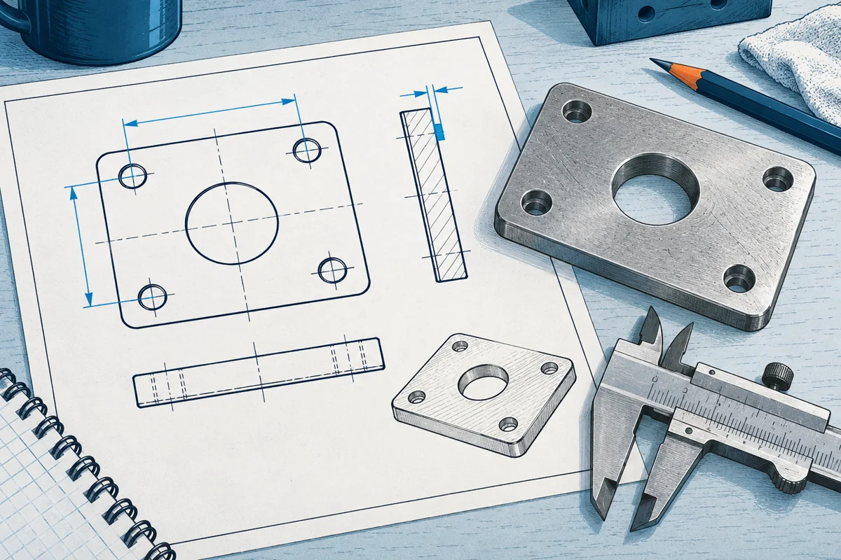
The drawing should explain what the model cannot
A model can show a pocket but not necessarily why its location matters. It can show a cylindrical surface without communicating the required fit or surface condition. The drawing connects geometry to manufacturing and inspection decisions. For a small invention, clarity matters more than visual complexity.
Start by identifying mating features, mounting features, moving interfaces, and appearance-sensitive surfaces. These are likely candidates for explicit requirements. A nonfunctional outside corner may need only the agreed general tolerance, while a locating hole may require a carefully defined relationship to the seating surface.
Autodesk organizes geometric tolerances into categories such as form, orientation, and location. Those tools are useful when ordinary size dimensions do not adequately describe function. They should not be added as decorative symbols. Incorrect datum choices or conflicting controls can make a drawing less clear than a simple, well-reasoned dimension scheme.
Establish identity and the basic manufacturing definition
Include a unique part identifier, revision, descriptive title, units, and sheet identification if the drawing spans multiple pages. Name the material precisely enough for the intended function, including grade or condition where required. “Aluminum” or “plastic” may be too broad for a meaningful quote or acceptance decision.
Specify finish in terms the supplier can act on and indicate exclusions. A coating on a sliding or electrical-contact surface may be unacceptable even when the rest of the part is coated. Color requirements may need a physical reference or an agreed system; a monitor screenshot is a poor acceptance standard.
State general tolerances and the controlling definition consistently with the supplier agreement. If a solid model controls undimensioned geometry, identify it by revision. If a drawing governs, ensure it contains sufficient definition. Do not allow a note to make two contradictory files simultaneously authoritative.
Dimension from functional references
Choose references that reflect how the part sits or locates in the assembly. Dimensions chained from one feature to the next accumulate variation differently from dimensions referenced to a common origin. The correct choice depends on function, not on which arrangement makes the drawing look tidy.
Use sections for hidden internal details and enlarged views for small features that cannot be read clearly at the main scale. Threaded holes need explicit thread information appropriate to the design. Do not expect a supplier to infer a thread from a plain cylindrical model or a sketch of a screw nearby.
Avoid duplicate controlling dimensions. If the same distance is specified in two places, a later edit can create a conflict. A reference dimension can provide helpful context when clearly marked as noncontrolling. Review the drawing at its intended print size; legible text on a large monitor can become unreadable on paper.
A hypothetical bracket drawing review
An inventor designs a bracket that mounts to two existing holes and supports a removable cover. The first drawing dimensions every outer edge but omits the relationship between the mounting holes and the cover seat. The manufacturer can reproduce the outline while still delivering parts that do not align the cover.
The revised drawing uses the actual seating face as a functional reference and defines the mounting-hole pattern relative to the relevant locating geometry. The cover engagement dimension receives a specific tolerance supported by a fit analysis. Decorative outside contours use the agreed general control. Exact values would depend on the real assembly and manufacturing method.
During review, the supplier notes that the requested inside corner is incompatible with its proposed milling cutter. The inventor confirms that a larger radius does not interfere with the cover and updates the model and drawing together. This is a productive manufacturability change because function, not appearance alone, guides the decision.
The inspection plan then checks the features that matter: mounting pattern, seating relationship, engagement dimension, and material or finish evidence where specified. It does not waste equal effort measuring every harmless contour while overlooking the functional interface.
Review the drawing as an inspector would
Ask how each critical requirement will be measured. Does the part have a stable seating arrangement? Is the feature accessible? Are the datum references physically meaningful? If a measurement requires specialized equipment, discuss that before ordering rather than after a disagreement.
Perform a consistency pass against the model, bill of materials, and intended assembly. Check units, revision, quantity of holes, thread descriptions, and finish notes. Have the supplier identify ambiguous callouts in writing. A question before manufacture is evidence of useful review, not necessarily lack of competence.
Keep the released drawing with the corresponding quote and purchase record. When a change occurs, issue a new revision and describe the affected requirements. A corrected local file does not update the copy already on a shop floor.
Your finished drawing should let a capable supplier manufacture the intended part and let an inspector judge the agreed result. If it cannot support those two tasks, adding more dimensions or symbols will not solve the underlying communication problem.