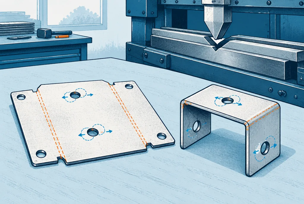
The flat drawing is not the finished geometry
A sheet-metal part begins flat, but its function usually depends on the formed condition. The location of a hole on a flange can be affected by bend position and angle as well as its laser-cut location. A long chain across several bends can accumulate variation that is absent from an ideal CAD assembly.
The CAD system's flat pattern depends on material and bend assumptions. If those do not match the supplier's tooling and practice, a mathematically valid development can produce the wrong formed dimensions. Ask the fabricator which definition it wants to control and whether it will generate its own flat pattern.
Protolabs' process guidance distinguishes tolerances across single and multiple surfaces, while its assembly guidance identifies features near forming regions that may need additional treatment. These are supplier-specific examples of why a formed assembly should not be treated as a flat plate with perfectly placed folds.
Identify the dimensions that make the bracket work
Mark the mounting surfaces, mating-hole pattern, clearances, and installed orientation. Decide which formed dimensions are critical and how they will be inspected. If the bracket must seat against two surfaces, their relationship may matter more than the exact flat blank length.
Avoid locating a critical hole near a bend without discussing deformation and access. The appropriate spacing depends on the actual process and material. A generic rule found online may be a useful question starter, but the supplier should confirm the proposed feature for its tooling.
Include hardware insertion, finishing, and assembly sequence. A fastener may need access before bending, or a coating may affect a fit. A theoretically correct bracket can still be difficult to assemble if the sequence is not considered.
A hypothetical bent equipment tray
An inventor designs a small tray with two side flanges and mounting holes aligned to an existing frame. The flat pattern is exported from CAD using default bend settings. The first formed parts have accurate hole diameters but do not align with the frame across the full width.
Inspection shows that the formed flange spacing and angle differ from the assumed geometry. The holes were cut where the file specified, so blaming the hole-cutting operation misses the cause. The inventor and fabricator review the material thickness, inside radius, bend sequence, and controlling dimensions.
The revised package identifies the frame-facing surfaces and the mounting relationship in the formed state. The fabricator confirms the flat-pattern approach for its process. Where a slot is considered to accommodate variation, the inventor evaluates whether it affects positioning or retention rather than adding it automatically.
The next sample is measured as a formed part and assembled to the reference frame without forcing it. The successful fit applies to the tested configuration and supplier process. It does not establish that any shop can use the same default flat file without review.
Separate design flexibility from uncontrolled variation
An adjustment slot can be a deliberate design feature, but it should have a purpose and limits. If the product needs precise location, simply enlarging every hole may trade an assembly problem for a positioning problem. Consider which feature locates the part and which accommodates variation.
Likewise, hand bending a prototype into place can support an early demonstration but should be documented. It may conceal a definition or process issue that will recur in a batch. Record the as-received condition before adjustment.
If several bends influence one critical interface, ask whether the design can reference fewer formed surfaces, use a different construction, or include a controlled adjustment. Such changes can reduce sensitivity more effectively than demanding exceptional accuracy from every bend.
The sheet-metal handoff checklist
Provide material and thickness, finish, formed geometry, critical dimensions, hardware requirements, quantity, and the intended mating reference. Confirm responsibility for the flat pattern and the accepted bend assumptions. Keep the model and drawing revision aligned.
Ask the supplier to flag features at risk of deformation or access problems before fabrication. Agree on inspection of the formed state and any assembly check. If the first sample requires correction, distinguish a design change from a process correction and update the records accordingly.
Your deliverable is a bracket definition that reflects how the part is actually formed and used. The most valuable drawing is not the one with the most dimensions; it is the one that protects the functional relationships through bending, finishing, and assembly.